
Connecting a 4-20mA Sensor to Your Control System
Published
The 4-20mA current loop is the backbone of industrial process measurement. Here's what you need to know to connect a sensor correctly and avoid the most common wiring mistakes.
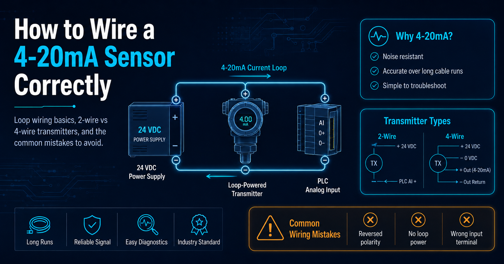
The 4-20mA current loop has been the dominant signal standard in industrial process control for decades. It's reliable, noise-resistant over long cable runs, and simple to troubleshoot. But connecting a 4-20mA sensor correctly requires understanding a few fundamentals — get them wrong and you'll spend hours chasing signal problems that should never have happened.
What Is a 4-20mA Loop?
A 4-20mA current loop transmits a measurement signal as a variable current rather than a voltage. The transmitter (your sensor) regulates current flow through the loop in proportion to what it's measuring. At the low end of the measurement range, the loop carries 4mA. At the high end, it carries 20mA. Everything in between is proportional.
The reason current is used instead of voltage is simple: current doesn't drop across long cable runs the way voltage does. A 4-20mA signal from a pressure transmitter 2,000 feet away arrives at your control panel just as accurate as one 10 feet away.
Two-Wire vs. Four-Wire Transmitters
Before wiring anything, identify what type of transmitter you have.
A two-wire transmitter is loop-powered — it draws its operating power directly from the loop itself. The same two wires that carry the signal also power the device. This is the most common configuration for field instruments like pressure, temperature, and level transmitters.
A four-wire transmitter has a separate power supply for the device and uses a dedicated pair of wires for the signal output. These are common on analyzers and more complex instruments that require more power than a loop can provide.
Wiring a Two-Wire Transmitter
For a two-wire loop-powered transmitter, the wiring is straightforward:
The positive terminal of your DC power supply connects to the positive terminal of the transmitter. The negative terminal of the transmitter connects to the positive input of your receiver (PLC analog input, indicator, or recorder). The negative terminal of your receiver connects back to the negative terminal of the power supply, completing the loop.
Loop supply voltage is typically 24VDC. Check your transmitter's datasheet for minimum and maximum loop voltage requirements — most two-wire transmitters operate between 12VDC and 36VDC.
Load Resistance
Every device in the loop adds resistance. Your power supply must provide enough voltage to drive the full 20mA through the total loop resistance. A simple way to check: add up the resistance of all devices in the loop (input resistors on your PLC card, barriers, converters) and multiply by 0.02A. The result must be less than your available loop voltage minus the transmitter's minimum operating voltage.
If you're running tight on loop voltage, a signal isolator or loop-powered repeater can help — and also provides the benefit of electrical isolation between the field device and your control system.
Grounding and Shielding
Ground loops are the most common source of noise and measurement errors in 4-20mA installations. The fix is to ground the cable shield at one end only — typically at the control panel end. Grounding at both ends creates a ground loop that induces noise into the signal.
Keep signal wiring away from high-voltage power cables wherever possible. If they must cross, cross at 90 degrees rather than running parallel.
Verifying the Loop
Once wired, verify the loop with a clamp meter or loop calibrator before commissioning. At zero input (minimum process), you should read 4mA. At full scale, you should read 20mA. If you're seeing less than 4mA, check for wiring errors or insufficient loop voltage. If you're seeing noise or instability, check your shielding and grounding.
A properly installed 4-20mA loop should be stable, repeatable, and virtually maintenance-free for years of operation.